First of all, while I ordered an update EPROM chip quite awhile ago, I had never installed it. It was not that hard, once I got up the gumption to do it. NCE had instructions on their website. First, I removed the four screws and slid off the cover. Being careful not to pry under the holder, the old chip popped right off with gentle prying with a small screwdriver from below. Following the instructions, I positioned the new chip using the half moon to guide the orientation. Two of the prongs tried to splay out rather than slide into their slots. As I was going slowly and carefully, I was able to remove the chip, straighten the prongs, and install the chip with all the prongs in place. Hopefully it was a successful install!

I sketched out several designs for a shelf under the layout to hold the command station, transformer, and power strip. I settled on one that basically has the shelf bolted to a support rail between two legs. I made the shelf from 1/2" plywood with a 2x2 glued under it. After painting everything a flat black, I bolted the 2x2 to the rail I had installed between the legs. In hindsight I should have used a 2x3 because the 2x2 left too narrow a space for my drill motor to fit at a true perpendicular for installing the carriage bolts. I ended up with rough framing tolerances rather than finish carpentry, but it worked.
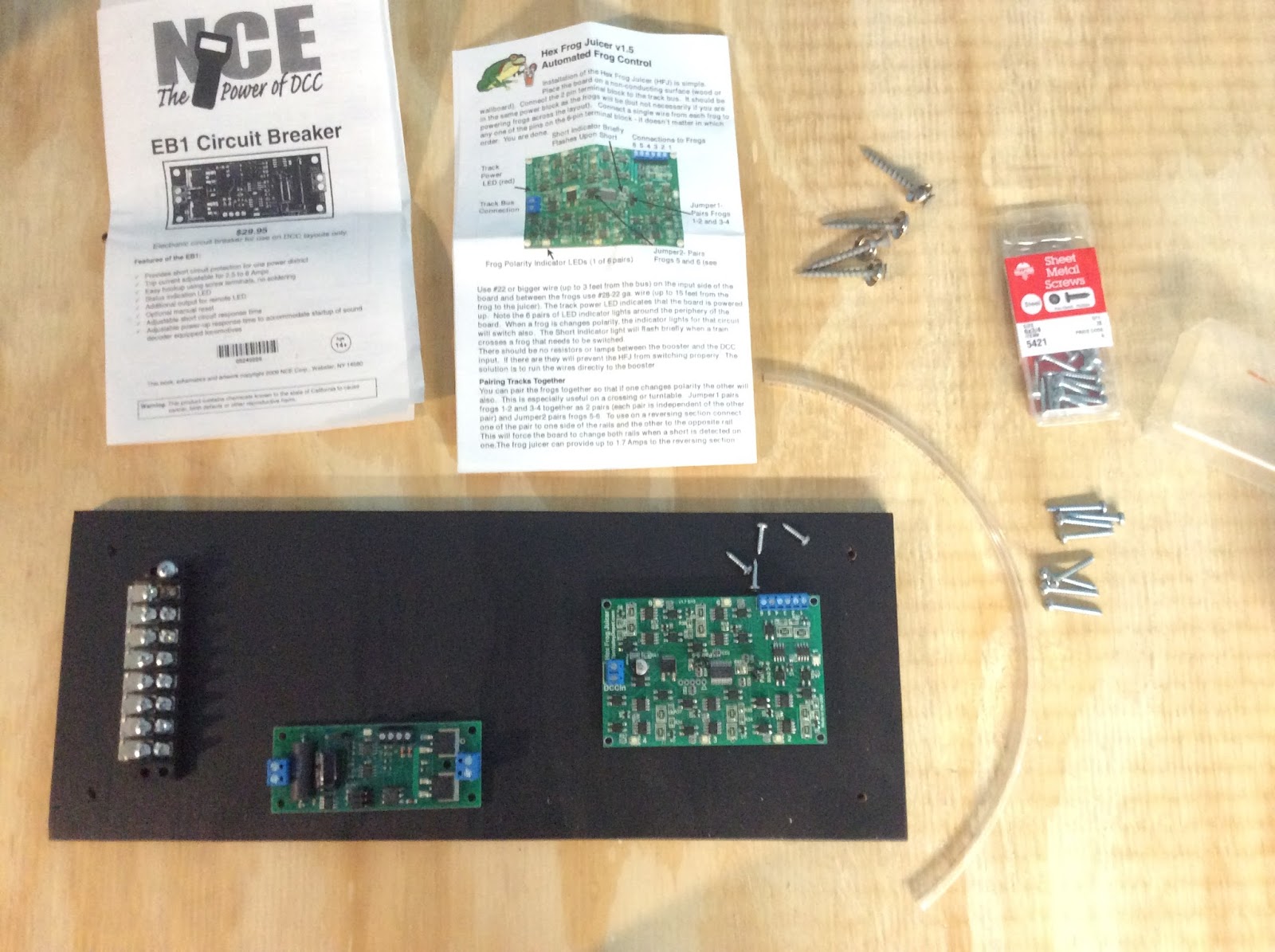
I used a barrier strip I had on hand, mounted with #6 1/2 inch pan head screws. For the EB1 boards I fashioned standoffs from plastic tubing and mounted them with #6 3/4 inch pan head screws. I set a stop on my NWSL Chopper at approximately 3/8" and cut all eight pieces of tubing to use as standoffs. The Frog Juicer had plastic bumpers already installed under the circuit board, but I had to find some #4 screws to mount it. While on the work bench I connected the one circuit board I have on hand and the Frog Juicer to the barrier strip..

The one thing that I haven't quite figured out yet is the location of a program track. I'm leaning towards adding it to the staging module. Then I could start the bus and power the staging tracks to use as test tracks and trouble shoot the system.
No comments:
Post a Comment