Sunday, December 4, 2016

Rolling Stock Standards

Workbench set up to check rolling stock standards
Now that I have at least a staging yard ready for rolling stock, I have started to unpack some of my rolling stock. Before any make their way onto the tracks I am checking them for damage and standards. As seen in the photo of my workbench, I have a test track set up with a re-railer and a Kadee coupler height gauge. Along with that I have a ruler with NMRA weights marked on it, a postal scale, and a NMRA standards gauge. With these simple tools I can check rolling stock. Of the six cars I unpacked today, one needed some repairs and several needed coupler adjustment or replacement. I have several hoppers and a gondola that are under weight without their loads, they won't receive car cards or make it onto the tracks until I have figured that issue out. As my standards aren't too different from my old modular group, I am mainly dealing with wear and tear as well as creating car cards.

Rolling Stock Standards:


  • NMRA weight or close
  • Metal wheels in gauge
  • Couplers: coupler and trip pin at correct height, smoothly centering, if replacing use Kadee 58
  • Cinderella principle for trucks (not too loose, not too tight)
  • Appropriate build date (before 1954?)
  • Car card created
  • Weathering--right now I am sorting between weathered and need weathered

Tuesday, November 22, 2016

Foundry Track Structure - Plant #4

Wanting to take a break from track laying and wiring, I recently started building Plant #4, a Walthers background building, as a structure for the foundry track at Willow Springs. While the building itself is a stock kit, I did design a scratchbuilt loading dock for it as a replacement for the supplied concrete steps.

The brick structure was fairly easy to build and has nice details. As the sides were molded in a different color from the front panel, a first step was to paint the wall panels. I used Rust-Oleum 2X Flat Red primer, which covered well without obscuring the molded brick details. The mortar wash was a combination of white and raw umber acrylic along with water and a spritz of window cleaner. The next time I apply a mortar wash, I plan to try 70% alcohol instead of water. After the wash dried I scrubbed the brick surface with a pink eraser to remove excess white.  As a final step in painting the brick walls, I toned them down with a slight application of Red Iron Oxide Pan Pastels. Before assembling the building, I painted the window sills and foundation parts with Concrete Flat Model Master. I painted the windows and door with Poly Scale Empire Green (actually a greyish dark brown). I ended up painting the roof panels this same color as I was unhappy with the coverage with Model Master's Grimy Black Flat. It would be excellent used as a weathering wash, but did not cover as a base color over the plastic roof panels. Other than modifying two of the windows, so that they appear to be open, I followed the instructions for construction of the model.

The loading dock for this structure was a simple introduction to scratchbuilding techniques. Basically, I used a process described by Gerry Leone in a Dream, Plan, Build video. The Walthers building parts and the existing cork on the layout provided the necessary measurements to draw up a plan. The scale size of the lumber for the dock was partially determined by what I had on hand: 6" X 12" for the framing, 3" X 12" for the decking, and 9" X 9" for the posts. I precut the pieces to length on my Northwest Shortline "Chopper".


Having a scale drawing to use as a template is key to this project. After cutting sufficient wood for the entire project, I stained it with my Prego Jar mix, 70% alcohol, India ink, and raw umber acrylic paint. While the pieces dried I taped the drawing down on my work space's plate glass with blue painter's tape. Then I covered the template with wax paper, also taped in place. The first step was to construct the frame directly over the template drawing. I used Aleene's Tacky Glue to glue the parts together. After the framework dried, I set up a backrest or jig as seen in the photo to the right. Then it was a straightforward process to apply glue to the top of the frame and attach five or six deck pieces at a time. After the decking dried, I turned the dock over and glued the posts in place. I later added the bracing to the front of the dock as a final flourish.

With the basic building and dock now constructed, the next step will be to add some additional detailing. At this point I am considering several options:

  • Filling the interior with a black construction paper curtain to hide the blue backdrop
  • Signage on the building
  • "Stuff" on the loading dock
  • A shadow box interior for a second floor "office"
  • A light over the door

Thursday, November 3, 2016

East Staging -- DCC and Independent Control of Staging Tracks

While it first appears straight forward to wire a small staging module, my East Staging section turned out to be somewhat complicated.
Wiring under the East Staging Module: DCC feeders,  DC bus,
individual track power control panel to the far right.
With sound decoders in each of the locomotives waiting on the staging tracks, I wanted to be able to turn the power off and on for each track. Since I also wanted to be able to identify whether the tracks had power by a visual signal, I needed to start a 12 volt DC bus on this module to power LEDs as well as building lights or other accessories on the rest of the layout. Finally, as noted in the previous post, I am starting a 12 volt touch-toggled, Tortoise switch machine bus at this module as well.

The first step was to drop feeders from each of the rails, either to connect to the DCC bus or a control panel for the staging tracks. After soldering the feeders to the outside of the rails, I painted the ties and track with a brown satin rattle can. After the paint dried, I cleaned the top of the rails and used a Dremel tool with a cut-off disk to cut gaps in the outer or "black" rails. Then I returned to the underside of the module and the construction of the track power control panel.

Schematic
Powering the feeders was not complicated, but the control panel took some planning. The schematic to the right was what I came up with. As the actual wiring starts to be a bit of a rat's nest, I wanted to keep some sort of record of what is actually going on. The panel itself was made from a scrap piece of masonite, with holes cut for sub mini slide switches (RS 275-0033) and LED assemblies (RS 276-0271)  from Radio Shack.

Control Panel Rat's Nest


To the left is the so-called rat's nest behind the panel. Black Wires from the DCC bus and to the track were soldered to one side of the DPDT slide switches, while the other side controlled the LEDs with connections (red and white wires) to the DC bus that originates at this modules.


While both the bill box and the track power control panel still need labeled, the East Staging tracks are live with independent control. Accomplishment of some trackage ready to run trains can be seen in the photo below.

Sunday, October 30, 2016

East Staging -- Turnout Controls and Track Diagram

One of the items on my list to get trains running, probably the most complicated, was to set up the East Staging module with wiring and control panels. While I did the DCC wiring first, this first post will discuss the turnout controls.

East Staging track diagram and turnout control panel supports
are in place but the glue is not dry yet.
While I had the module built and Tortoise turnouts installed, the module had no wiring. I intended to set it up with the ability to turn the power off and on to individual tracks. Initially the plan was to have one control panel for controlling track power and turnouts, but drilling the plexiglass was intimidating to me, and I didn't want to buy special drill bits. I saw an advertisement for touch toggles in a recent Railroad Model Craftsman magazine and after looking at Berritt Hill's website, went ahead and ordered the parts to control the two turnouts. As the turnout control panel would be mounted on the fascia, I also cut and mounted a hardboard fascia to the staging module. Part of my rationale is to try out this touch toggle and track diagram system and potentially use it later for the seven turnouts on the other side of the layout. When it is time to tackle the Willow Springs side of the layout, I will order DC extension cables as well as another base unit and additional touch toggles. My understanding is that I will be able to daisy chain out from this initial set-up.

For this staging module, I initially ordered a 12 volt power supply, a 2 output direct base, and a pair of one-light-red-green touch toggles.

Installation was fairly straight forward. The two wires from each switch machine screw into the blue connector seen at the top of the base unit, which I mounted to the fascia with #6 x 3/4 screws. The toggles also plug into the base unit, as does the power supply. Then the toggles just tape in place behind a printed control panel mounted in an inexpensive frame. If the red-green LED does not initially coordinate with the track plan, it is easy to switch the two wires in the appropriate blue connector.

While writing this post, the glue has dried, so I will go paint the supports that I cut out of scrap plywood. When the paint has dried and I have mounted the frame, I will have a labeled track diagram with snazzy color-coded touch toggles.

Wednesday, September 28, 2016

Setting Up the DCC System Part 3: Bus Wires

The first small step taken for reaching the goal of running trains by the end of October was to run the DCC bus wires.

I described setting up the DCC system with two circuit breakers, NCE EB1s, dividing the layout into two power districts in an earlier post. In the photo above, one can see the bus for each with the end of the eastern power district visible towards the front of the layout. Each bus is made up of a pair of #14 red and black wires. Black out, or towards the aisle, is the protocol that I have established for consistent "polarity," and I drilled holes in the supports to allow room for my plan to use suitcase connectors to attach the feeder wires.

The photo to the left shows the end of the "Power District West." I terminated this bus at a European style terminal strip or barrier strip. After the drop down staging has been designed and built, it will also be powered by this power district. All I needed to do at this end of the bus was to tin the stranded #14 wire before screwing it into the terminal strip. For the standard barrier strips I soldered on #6 spade connectors.


The photo to the right shows the "tee" for "Power District East." The bus begins at a circuit breaker on the other side of the panel and then separates into the two sides of the top of the "tee" at the barrier strip. I decided on this approach as the circuit breaker is located in the middle of the power district. 

The photo to the left shows the east end which terminates in a barrier strip and a Molex connecter. As the staging module that connects to the layout at this end already is set up with a Molex connector, I decided to stay with that system here. 

At this point the bus wires are installed for the DCC system. No matter where I decide to start laying track and wiring it, the bus is set up and ready.

Friday, September 23, 2016

Plan for October

Well, we are back from vacation, wife's family reunion in New Jersey and Civil War battlefields in Virginia, and it is time to make some actual progress on the layout. Since the last post in August, I have gone down several rabbit holes with the railroad. I started exploring the standards I will follow for rolling stock, thinking about the logging road that interchanges at Willow Junction (will it have custom decals? what will the numbering system be?) and researching more about supporting industries. In addition to these sidetracking issues, I had a problem with overlapping goals and being unsure how to  order them.

I think that the best approach to make some progress is to set a specific goal and determine a clear set of smaller steps in order to accomplish said goal. The goal is: Be able to run trains by the end of October.  The following list is a draft of the so-called smaller steps. While it is tentatively in the order that I intend to follow, I may have to adjust the order. Neither wiring or track laying are my favorite hobby activities, but I really need to focus and try to achieve this goal without allowing myself to be too distracted with other activities such as scenery, rolling stock, structures, or operations.


  • DCC bus to Willow Springs side of layout
  • DCC bus, a "tee" out to Willow Junction side of layout
  • Install the program track and some associated track around Willow Junction
  • Wire the program track and switch
  • Test first tracks
  • Prep wye turnout for box company spur
  • Set up Switch It and maybe the button controls for Willow Springs side of layout
  • Order Tortoise motors
  • Prep turnouts for Willow Springs side, use techniques from previous post and remove springs
  • Finish track laying and wiring for Willow Junction
  • Temporary bridge using section track
  • East staging wiring, control panel, and DC bus
  • Track laying and wiring for Willow Springs
  • Cab bus and plug ins wired
  • Control panel for Willow Springs
  • West staging built

Monday, August 15, 2016

Preparation for Laying Track

With the backdrops painted and the cork down, it is time to actually lay the track with the goal of actually running some trains. I will take a how-to approach to this post as I am trying some new techniques and I am learning how to do some of this myself.

Prepping the Cork for Turnouts

Materials                                     

  • Scrap cork
  • Hobby knife 
  • Hobby knife with #17 blade
  • Machinist's square
  • Scale rule
  • Sharpie
  • Sanding block 
  • Wood glue
  • Drill with 1/4" bit
  • Flat black latex paint
  • Grey latex paint similar to ballast color
  • 1" bristle brush
The switch stand pads are made from scrap cork, turned upside down so they slide into the bevel. I trimmed mine to an eight scale feet width. I beveled the three sides first with a hobby knife and then a sanding pad. I glued them in place with wood glue, centering each of them with the tie rod lines that were already marked next to the cork.

After glueing the switch stand pads in place, I cut slots for switch machine actuating wire. While I do not plan on using switch machines on the side of the layout I started on today, I went ahead and prepped for them in case I ever change my mind down the road. (It is nearly impossible to drill out the holes after the fact without tearing up the turnouts.) The first step is to mark a rectangle on the cork approximately 1/4 by 1/2 inches, centered along the mark for the throw rod. The next step is to cut out the cork with a #17 chisel edge blade. Finally, after removing the cork, drill two 1/4" holes and use the drill to connect them into a slot.

At this point, it makes sense to paint under the turnout locations. By painting the cork a flat black or a close approximation of the ballast color under the point rails, one can avoid ballasting (or at least heavy ballasting) under the path of the moving point rails. Also, in this area, I had patched the cork with white spackle and the paint will hide any white showing through.

Prepping the Turnouts

                                                                                                                                                               
In addition to the tools needed for prepping the Peco Electrofrog turnouts, one can see the painted cork with turnout pads ready for the track in the photo to the right.
  • rail nippers
  • wire cutters
  • wire strippers
  • needle nosed pliers
  • hobby knives
  • jeweler's files
  • #20 wire
  • solder, rosin, soldering iron
  • solder stand with alligator clips
  • drill with 1/8" bit
  • pin vise and twist drill bits
  • multi-meter

The Peco Streamline Electrofrog turnouts that I am using need a few adaptations for independently powered frogs and DCC "friendliness." A clear discussion of these turnouts can be found on the DCCwiki. The steps I am taking for Willow Junction are below. Again, I am not using switch motors on this side of the layout, but I am powering the frogs with a Tam Valley "Frog Juicer." Steps 1-5 are preparation before laying track, and 6-10 are part of the track laying process. 

Peco Elecrofrog with first three modifications done
  1. Snip the wires connecting center rails to frog. (The gap is already there in Peco Streamline Electrofrog; in other brands one needs to cut a gap in the rail.)  
  2. Solder the point rail to the stock rail for the mainline and diverging rails at the gaps in the plastic tie material under the turnout.
  3. Solder feeder rail to frog. Since I already have a "Frog Juicer" installed, I made sure the wire would be long enough to reach it.
  4. Construct a wire jumper to bridge the hinge at the point rails. David Popp has instructions on MRVP Olympia Layout. While I understand the rationale for having this, I find that my first attempt is unsightly and detracts from an otherwise attractive turnout. 
  5. Check continuity with a multi-meter. Ohms will show continuity. Frog should be isolated (no continuity with other rails). Stock and closure rails should have continuity, but just on one side. No continuity between mainline and diverging routes.
  6. Measure and locate position before drilling 1/8" hole for feeder wire through the cork.
  7. Trim head block ties if switch stand is located on opposite side.
  8.  Trim ties for rail joiners as necessary.
  9. Drill out ties for track nails from back side if desired.
  10. Remember to use insulated rail joiners after the frog! It is a built in short if you don't do this.

I am curious what others think about the need for a prophylactic wire jumper to bridge the point rail hinge, my step 4. Please comment!


Saturday, August 13, 2016

Backdrops Part 3: Background Landscape

Painting the background, other than sky, requires some research to match the appearance of the location that one is modeling. If it is not a reasonably close-by location, some internet tools can be very helpful. Three that I have found useful are Google Earth, Wikipedia, and on-line real estate photos. Because I was taking a trip to the Pacific Northwest to finish up some final aspects of our move to Pennsylvania, I was able to fit in some in-person research. Traveling parallel to the route of the 3rd Subdivision between Anacortes and Burlington and driving around Ferndale, gave me the opportunity to take some snapshot-quality photos as reference.
Mountains, trees, and field west of Ferndale


The first step in actually painting the backdrop was to pencil in some lines for background mountains, hills, and trees. Another step before actually painting was to mask off the bench work, cork, or any of the DCC components with newspaper and blue tape. One of the techniques I learned from one of my modular railroad friends in Seattle was to spray white haze between layers of hills to add depth to the scene. I wanted to protect the surroundings as I attempted that technique with a flat white rattle can.


This shot, to the left, shows three layers of hills with white spray paint between the more distant layers and behind the tree line. In this part of the painted background I kept the horizon low and the colors muted with the only real detail in the subtle conifer brushwork at the top of the ridges. These are three of the colors that I premixed with the intent to use them throughout the initial layout and any later extensions that I might add in the future. I used the sky blue and white latex paint as well as adding some craft paints colors (slate grey and medium foliage green) and raw umber Liquitex acrylic.

The shot to the right shows both the beginning of a signature scene, Mt. Baker, and the array of brushes that I used. In one of the coved corners I wanted to include Mt. Baker because it is definitely a recognizable feature in Whatcom County, at least on a rare blue sky day. Of all those brushes, the two that I used the most were a #8 bristle round and a #2 bristle flat. I used a larger bristle flat to create the treed texture at the top of some of the ridges and a softer flat and a fan brush for some closer tree work. But really, I could have gotten by with just the two.

In this shot, to the left, my attempts to layer details while keeping a low horizon line are shown. At this point, I have completed painting the background landscape for the backdrop of the initial "U" shaped layout. As I add foreground scenery and complete the final step, disguising the right angle between the backdrop and the benchwork, I may have to go back and make some adjustments or additions to the painted backdrop.


Friday, August 5, 2016

Progress Update

Willow Springs side of the "U" with cork installed
Some serious progress has been made on the layout in the past month or so. The benchwork, track plan, and cork are complete (other than the fold-up, west end staging) for the initial U-shaped layout. Likewise, the backdrop is complete with sky. Now the next steps are to add detail to the backdrop and to install and wire the track.

Tuesday, July 12, 2016

Planning for Operations

While track is not yet installed on the layout, planning for operations is definitely part of the process, even at this stage. Once the track plan had been finalized by mocking up the Willow Springs side in place, I adjusted my scale track plan to incorporate those changes.

Revised track plan with Willow Springs to
the left and Willow Junction on the right

Version 2.0 and Naming the Tracks


With the track plan finalized, I was able to name all of the tracks.   Many model railroad writers, such as Tony Koester and Andy Sperandeo, suggest this as a way of making both the layout and operations on the layout more authentic.

The original plan for Willow Springs had a warehouse located along the siding, which in prototype practice would not have cars "parked" along it. The purpose of a siding is as a passing siding for meets or as a runaround; neither of these would be easily accomplished with a boxcar left at the warehouse. In this second iteration, the siding is able to function as a siding.


First draft of timetable and system map

Location On a Map


Earlier this spring I spent some time figuring out the location of the freelanced 4th Subdivision with its combination of fictional and real locations. Ferndale is a real town located along the GN mainline, now the BNSF. The Fourth Subdivision travels from the fictional Port Gulick Bay, located near the real Lumni Bay, through the lowlands towards the foothills and ultimately into the Cascade Mountains. Nooksack is a real location, while Willow Springs, Curtis, Chikamin (Chinook jargon for metal), and Green Rock are fictional names.

In addition to adding the 4th Subdivision to a prototype Great Northern system map, I also created a first draft of a timetable for a scheduled passenger train. Not only will locating the layout on a map help with orienting the movement of cars, but it will also help with creating appropriate and realistic scenery.

Sunday, July 10, 2016

Finalizing the Track Plan

Now that the benchwork and backdrop for the layout are in place, I am able to revisit the Willow Springs side of the "U" and shift to a focus on starting the trackwork. It turns out that I did make some changes from my initial plan based on mocking up the plan full size on the benchwork.

Mocking up the track plan at Willow Springs
Along with shifting the location of a couple of turnouts, the major change was to add a second  spur off of the passing siding. While I had already obtained the turnout needed to add a team track spur, I found that I will need some additional cork and flex track. Those are now ordered and I have penciled in all the track center lines and turnout locations for the revised track plan. With the track plan finalized, I installed the cork for the spur and curve leading from Willow Junction to the trestle at the base of the "U" completing the cork roadbed on that side of the layout.

New tool added to my roadbed installation toolkit
While I followed the procedure for laying cork mentioned in an earlier blog post, I found that a small machinist's square is an essential tool for making perpendicular cuts in the cork. Also, now that they are available,  I find using  commercial turnout pads definitely save time, but they do add to the expense. With the trackwork plan finalized for the entire layout, I can continue to make my way with the cork roadbed and set up my workbench for modifying the turnouts.

Monday, July 4, 2016

Backdrops Part 2: Painting the Sky

After prepping the seams, painting the sky is the second step on the backdrop to the layout. Rather than just painting a sky blue color, I blended the sky blue color into white at the base of the backdrop to simulate the haze at the horizon. The initial effect seems a bit stripy, but more background will be added along the horizon later.


I used a small roller for the blue and a brush to apply the white and blend the two. I painted both colors in about a four foot section and blended the white into the blue before moving into the next section. This way the edges between colors and sections where wet when I moved on to the next area.

After the first coat dried overnight, I found that some areas did not have full coverage over the dark brown masonite. The blue is one of the newer paint and primer paints, but it still needed a second coat. Multiple coats can help with the blending from one color to another, so no harm, no foul. A handy tool for backdrop painting is to cut out a corner of the top of a milk jug to make a brush wash station. One is visible in the river cut out in the back of the photo to the left.


Another handy trick for backdrop painting is to seal the roller in a zip lock plastic bag. The photo to the right shows the roller sealed up overnight between the first and second coats. It was ready to go the second day; no muss and no fuss!


While I was painting the second coat, I added some clouds above the haze layer. Basically I blotted some white into the blue with a wadded paper towel. Then I repeated the blotting action to blend the white and wet blue to give it a more translucent or cloud-like look.

Now the backdrop is ready for nearer mountains, hills, and trees. More about the research, planning, and execution for that in Part 3.

Friday, July 1, 2016

Prepping the Backdrops

Now that the benchwork is complete and the backdrops are up, the next step before painting them is to tape and mud the seams using wallboard supplies. I purchased the smallest tub of joint compound and shortest roll of tape I could find along with an inexpensive set of plastic taping knives at the big box store.
One of the three seams to be sealed

The backboards on the layout are tempered hardboard (Masonite) ripped at 16" with 12" visible above the back of the layout. I mounted them to the back of the frame with screws and washers. At the seams I glued a piece of scrap "one by" wood to tie the two pieces together. I will prime the back of this last section when I finish the seams and have the primer out to paint the joints.


After sanding the edges on the front of the seam, I installed
fiberglass tape and the first coat of mud. The photo to the right was taken after I applied the first coat of mud. While the actual work time has not been much to speak of, this process takes one day for each layer to allow the joint compound to dry over night. I sanded, vacuumed up the dust, and wiped down the joint with a damp cloth between each coat.


The photo to the left is after the third (and hopefully final) coat was applied. For each coat I used a wider knife. After it dries, I should be able to sand and then prime the area around the joint before proceeding to actually painting the backdrops on the layout.

Saturday, June 25, 2016

Progress on the To Do List

While I haven't posted anything in quite a while, I have made some progress on the layout. The benchwork is basically complete except the fold-up staging, the backdrops are up, and the wiring for the programming track has been figured out and started.

Willow Junction with backdrops up and
a view of the program track control switch.
During the first weeks of June, I finished the open grid table for the second side of the "U". With my wife's help, we moved it from the wood-shop in the barn up to the attic. As I am considering using David Popp's fold up staging idea from MRVP's Tar Branch, I used a sightly different design for the lower bracing on the legs. I am still not sure of my final design for the fold up staging. We will see how that works out. At any event, I finished the legs and installed the final piece of benchwork last week.

Willow Springs switching district benchwork up, leveled,
bolted together, and backboard installed.


I am trying to compensate somewhat for changes in temperature and humidity in the attic by priming the underside of the benchwork sections and the back of the tempered hardboard backdrops as they are installed. I still need to tape and mud the joints between sections of the hardboard before I prime and paint them.

Now that the benchwork is complete on the second side of the layout, I can mock up my track plan in place. I already have some questions and potential changes from my initial plan.


So, here is my "To Do" list from April with changes (or not) . . .

To Do:
  • Benchwork finalized and in place   Done, check it off!
  • Backdrops finalized: seams, primed, and blue
  • Workbench and materials organized   Ikea rolling cart put together and some materials organized, but still more boxes and clutter to deal with
  • Regular posting to the blog    Not so much, gotta work on that!
  • DCC components set up   Yes, but now replace with bus wires installed
  • East staging and a program track wired  Started, but I need to finish
  • Start work on rolling stock and loco roster and maintenance
  • Start some track work    Connection to East Staging and interchange will be the focus
  • Full size mock up of Willow Springs switching district 
  • Start a building or bridge    Started plans and construction for curved trestle, need to get back on this
  • Design the fascia and valence    Some ideas, but I need to firm up with cardboard templates. 
  • Along with valence, figure out the lighting

Tuesday, April 26, 2016

Setting Up the DCC System Part 2

Following up on the previous post, the second EB1 circuit breaker board arrived from NCE, and I installed it. Since all three components were attached to the command station, I fired it up. Everything  (including EPROM install) appears successful since the system "talked" to my throttle.
Panel with power district circuit breakers and Frog Juicer
connected to command station!
While at first I was thinking of having the program track on the staging module, I have since decided on locating it on the interchange track for several reasons:

  • It will be located right over the command station, hence good location for control panel/switch.
  • I'm leaning towards ending interchange track with mirror rather than extending it into staging.
  • I can set up programming track before finishing staging module and complex backdrop.
In researching the wiring for my DCC program track, I discovered that just having a DPDT that switches an isolated (insulated) section of track between track power and programming is potentially dangerous. If a locomotive bridges the two while in programing mode,  it can damage the programming circuitry. Including an isolation or dead zone section between the programming track and the rest of the layout is the solution. I found several helpful sites for explaining the rationale and process:
According to the experts I needed a 4PDT switch to wire the program track with an isolation track. I ended up ordering one from mouser.com, a 633-S43 4PDT ON-OFF-ON. 

Monday, April 18, 2016

Setting Up the DCC System

Over the last few days we have had some beautiful spring weather, and in addition to doing some yard work, I have gotten up into the attic to work on the layout. Now that several of the sections of benchwork are fully installed, I tackled setting up the DCC system (NCE Power  Pro 5 amp) that I brought from Seattle.

First of all, while I ordered an update EPROM chip quite awhile ago, I had never installed it. It was not that hard, once I got up the gumption to do it. NCE had instructions on their website. First, I removed the four screws and slid off the cover. Being careful not to pry under the holder, the old chip popped right off with gentle prying with a small screwdriver from below. Following the instructions, I positioned the new chip using the half moon to guide the orientation. Two of the prongs tried to splay out rather than slide into their slots. As I was going slowly and carefully, I was able to remove the chip, straighten the prongs, and install the chip with all the prongs in place. Hopefully it was a successful install!


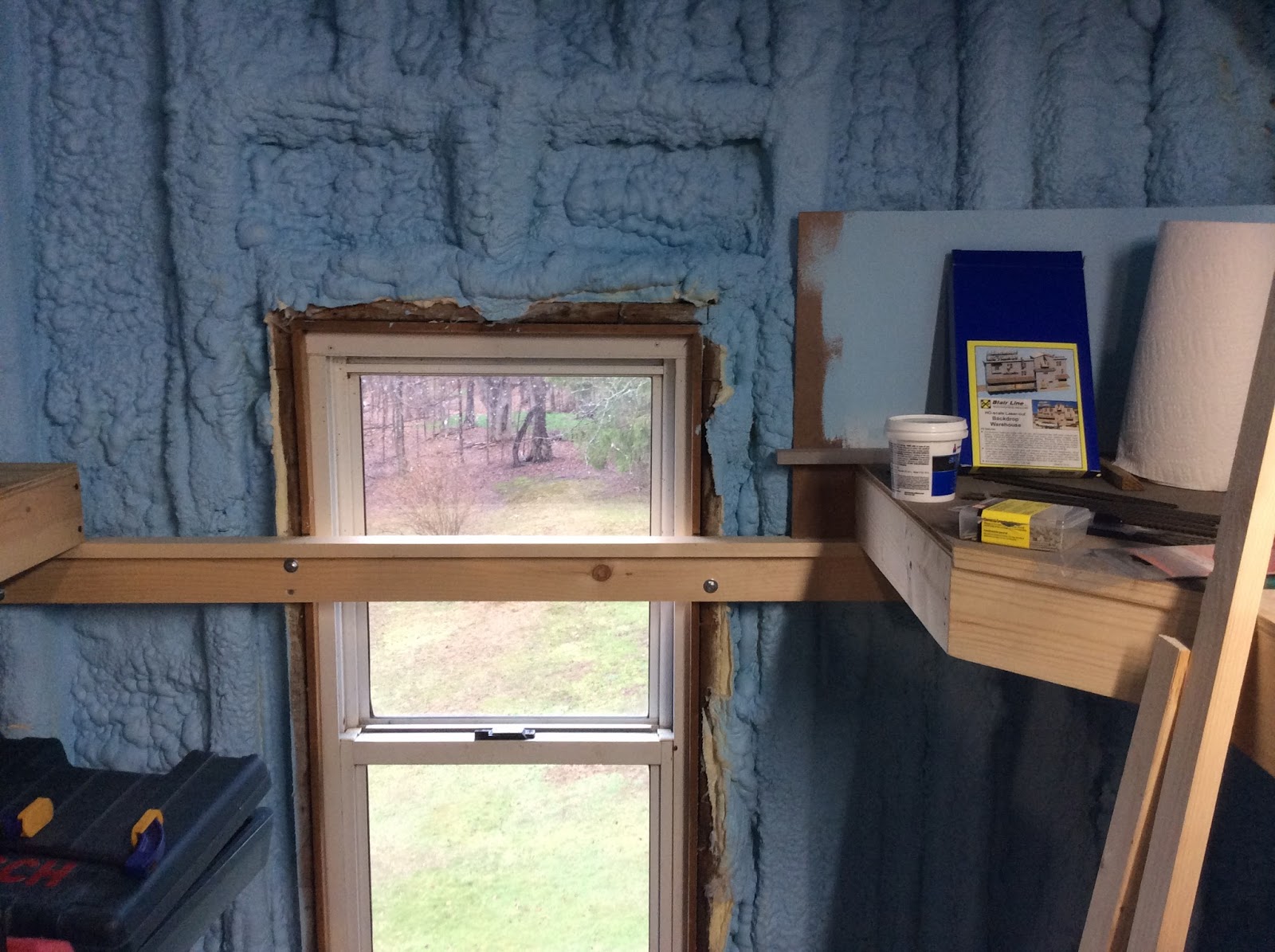
I sketched out several designs for a shelf under the layout to hold the command station, transformer, and power strip. I settled on one that basically has the shelf bolted to a support rail between two legs. I made the shelf from 1/2" plywood with a 2x2 glued under it. After painting everything a flat black, I bolted the 2x2  to the rail I had installed between the legs. In hindsight I should have used a 2x3 because the 2x2 left too narrow a space for my drill motor to fit at a true perpendicular for installing the carriage bolts. I ended up with rough framing tolerances rather than finish carpentry, but it worked.


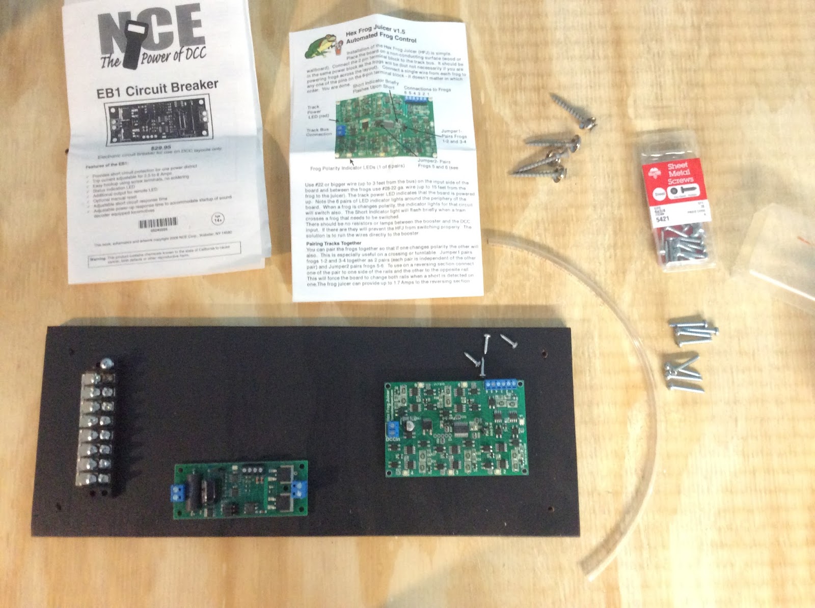
The next step was to build a  board to mount some of the components of the system. For this initial U shaped layout, I am planning on having two power districts with each protected by a circuit breaker. This board, made from scrap plywood, was designed to hold the two NCE EB1 breakers (I need to order a second one) as well as a Tam Valley Depot Hex Frog Juicer to power the frogs of the turnouts in the interchange yard.

I used a barrier strip I had on hand, mounted with  #6 1/2 inch pan head screws. For the EB1 boards I fashioned standoffs from plastic tubing and mounted them with #6 3/4 inch pan head screws.  I set a stop on my NWSL Chopper at approximately 3/8" and cut all eight pieces of tubing to use as standoffs. The Frog Juicer had plastic bumpers already installed under the circuit board, but I had to find some #4 screws to mount it. While on the work bench I connected the one circuit board I have on hand and the Frog Juicer to the barrier strip..

After mounting the board to another pair of legs, I ran the DCC output wires from the command station to the terminal strip. The system is ready for me to start the bus for the first power district and order the second EB1.

The one thing that I haven't quite figured out yet is the location of a program track. I'm leaning towards adding it to the staging module. Then I could start the bus and power the staging tracks to use as test tracks and trouble shoot the system.


Thursday, April 14, 2016

Goal Setting

While I have been occupied with other parts of my life over the last several months, I think that the slowdown in progress on the layout had a deeper cause. In a recent post on one of his blogs, Shelf Layouts, Lance Mindheim talks about "subtle traps that can sap enthusiasm." One that he mentions in particular is "not hitting personalized completion milestones" in our internal timeline. His solution is to front load with targets.

Mindheim Targets:

  • Benchwork Complete: 3-6 months
  • Some Train Running:  3-6 months
  • A scene or two finished:  1 year
  • All three:  18-24 months
With his targets in mind and an awareness that I have to fit the railroad in with other parts of my life without progress coming to a standstill, I have come up with a list of my own. It is intended as both a to do list and a goal setting motivator.

To Do:
  • Benchwork finalized and in place
  • Workbench and materials organized
  • Regular posting to the blog
  • DCC components set up
  • East staging and a program track wired
  • Start work on rolling stock and loco roster and maintenance
  • Start some track work
  • Start a building or bridge
  • Design the fascia and valence 

Tuesday, April 5, 2016

Benchwork for the Bottom of the "U"

Progress has certainly slowed over the winter; however, the benchwork for the bottom of the "U" is in place temporarily. As I mentioned in an earlier post, this section had to be slightly reduced in size from the original plan. I drew up plans with the new size continuing with basic open grid framing. One nod towards cookie cutter benchwork in this section is the cutout for a creek bed, a scenic element, between Willow Junction and Willow Springs.

Bottom of the "U" Benchwork under construction on sawhorses
in the attic. The workshop in the barn has been too cold!
This cutout turned out to be a bit of a gumption trap as I hadn't really tried cookie cutter benchwork before. The open grid frame itself was constructed in the traditional manner, with the exception of a 1" X 2" frame member supporting the creek bed. After cutting the plywood, I cut the frame down for the creek bed insert and attached 1" X 2" supports along the bottom of the front and back of the frame. Both the location of the future pile trestle and the triangular plywood extension are visible in the photo to the left. This side of the bottom of the "U" will not have a corner section; rather, it will be the two rectangles bolted together.

The plan is for the back of this section of the benchwork to rest on an L girder ledger with one leg supporting the front and the ends bolting to the adjacent sections.  I will need to trim some of the blue foam and mount the next section of backdrop before permanently installing this section. The ledger and the location are visible in the photo to the right.

Friday, January 22, 2016

Rationale for the Railroad Part 3 - Planning for Operations

The railroad will be a part of a freelanced 4th Subdivision of the Cascade Division of the Great Northern. The 4th Subdivision travels eastward from Port Gulick Bay, intersects with the North/South GN mainline at Ferndale, WA, and then travels into the Cascade Mountains to the town of Greenstone. Port Gulick Bay, on the Puget Sound, has potential for a small shipyard, bulk petroleum operation, lumber shipping, log dump, lumber mills, and canning operations. Located in Whatcom County, and inspired by the 3rd Subdivision in Skagit County, the railroad has a heritage of support to timber and agricultural production. Plus, in a totally fictional history, a rich series of veins of ore were discovered in the Cascade Mountains, near the Badger River, leading to the founding of Greenstone and several mines. Copper and silver ore continue to be mined into the 1950's with the ore shipped by rail to the smelter in Tacoma.

The first part to be built is an interchange junction of the 4th Subdivision with the Puget Sound and Badger River Railway, a logging road inspired by the Puget Sound and Baker River RR, east of the Mainline at Ferndale, but still in the valley/lowlands. The interchange is at Willow Junction and the initial layout also includes Willow Springs, a station on the 4th Subdivision. Willow Junction includes a small yard and engine facilities for the road switcher stationed there. Willow Springs includes several  opportunities for switching.

First-draft track plan: Willow Junction at the top with Willow Springs at the bottom.
Among the possibilities for industries at Willow Springs are a box factory, canning company, produce warehouse, grocery distributor, team platform, fuel company, freight house, and small foundry. Any of these have prototype examples in the lowlands of Skagit or Whatcom counties. While not shown on the track plan, staging will be provided at both ends of the "U" shaped initial layout.

The operating scheme is designed for solo operations or operations with two or three operators. Car movements will be orchestrated using car-cards and waybills as well as switchlists. Train movements will essentially be sequence operation, although a time element could be added. One small scheduled passenger train will pass through Willow Springs eastward and then return later in the day. One scheduled freight, a turn from Port Gulick Bay will pass through daily and return.  The turn may drop off or pick up cars at the runaround, while the Willow Junction road switcher will be in charge of  spotting the cars and blocking cars for pickup.


Monday, January 11, 2016

Cork Roadbed

Over the past week or so I have started the trackwork on Willow Junction (one side of the U-shaped initial layout in the attic) by laying cork roadbed for this small yard and interchange. In this post I will attempt a "how to" approach to the process.

Materials

Materials needed to lay cork roadbed

  • Cork
  • Sanding block
  • wood glue
  • small nails
  • needle nose pliers
  • hammer
  • paper towels
  • utility knife with sharp blade
  • pencil and sharpie
  • metal rule
  • putty knife
  • spackle
  • brush or shop vac


First Steps

  1. Make sure all track center lines and turnout locations are marked on the sub-roadbed (plywood in my case.)   
  2. Split the cork.
  3. Glue down the cork strips (with the bevel to the outside) following the centerline and then tack in place with small nails just into the plywood. Remember, the nails will be removed after the glue dries.
  4. Offset the cork strips to avoid ends butting side by side.
  5. For turnouts glue and tack just the outer strips.


Turnouts


For the interior of the turnout, measure by overlapping and then mark with a pencil or sharpie in order to make an accurate cut.  The cut will first be a taper and then trimming the bevel of the cork so it fits between the existing cork strips. I found that I was fitting the cork strip that followed the divergent route first before the strip following the straight. Both should be test fit and adjusted before glueing either of them in place.

Finishing Up the Cork

  1. Allow the glue to dry overnight and remove the small nails.
  2. Sand the bevel to remove the ridge left along one edge after splitting the cork in half. Some people recommend doing this before installing the cork, but I find it easier to do after the cork is glued in place. Just make sure it is done before painting the cork or installing track. 
  3. Spackle any gaps in the turnout splice work. I spackled the nail heads in the plywood at the same time.
  4. It might be a good idea to paint the cork at this time, at least flat black under turnout locations. On the other hand, it might be prudent to finalize track placement and drill holes for turnout controls before painting.

Special Applications for Willow Junction


The two yard tracks were trimmed square as they were glued down, while the mainline cork offsets the plywood for later final trim when staging is attached.

The cork abuts a cedar shim as the interchange towards the front will be code 70 track representing the Puget Sound and Badger River Railroad, a lumber line.

The cork for the siding in the back abuts the piece of gatorboard that will be the base for the construction of a small engine house. I learned this technique from Pete Gulick, one of my modular railroad friends in Seattle.