Saturday, October 27, 2018

Car Forwarding on the 4th Subdivision - Part One: Overview

Willow Springs Bill Boxes
After prepping for part of a mini-presentation on car forwarding at the October Division 12 membership meeting, I realized that I have never really documented the car forwarding process used on my model railroad here. The entire car forwarding process includes both initial planning and actual implementation. This process is what I have used for the initial "fun for one" operations plan as well as what I will continue to use as I plan for a more involved operations plan as the layout expands in the attic.

Switch List and Mini-clipboard
My car forwarding consists of a series of steps, presented here in roughly the order I followed in developing the initial "U" shaped layout.  The proto-freelanced nature of the 4th subdivision of the Cascade Division of the Great Northern led to research of industries ranging from the real to the plausible. After researching to establish potential industries, the car flow was developed or organized using two charts, an online industry list and a matrix chart of daily car flow. Then, moving from planning to implementation, a car card and four cycle waybill system was set up for the initial rolling stock, and bill boxes were installed and labeled for all the tracks. Finally, I have found that switch lists are a helpful car forwarding tool in some steps of the sequence operations I wrote about in the last post.

Having established an overview in this post, I intend to go into more depth for each of the steps in a later second part.

Tuesday, August 28, 2018

"Fun For One" Operations on the 4th Subdivision

NP Interchange and Willow Junction Yard
Although I have recently engaged in a lot of armchair modeling, planning for a larger operating scheme for extensions into the rest of the attic, the initial "U" of Willow Springs, Willow Junction, and associated staging is ready for "Fun for One" operations. The "Fun for One" concept, from Bryon Henderson, is explained in one of my original rationale posts. Yesterday, I took this section of the 4th Subdivision through several steps of my current operational plan:

Sequence Second Draft     4thSubdivision
“Ops – Fun for One”
Willow Springs and Willow Junction
(All Within Yard Limits)
·     Road Switcher works in yard limits
·     Passenger 288 Eastward and 287 Westward
·     Greenrock Turn: Extra Freight Leaves Port Gulick Bay to Greenrock and returns

1.   8AM Road switcher on duty: Service as needed and collect cars from NP Interchange.
2.   Greenrock Turn Eastbound leaves west staging, drops off and picks up on WS Siding before continuing on to interlocking signal, and enters East staging.
3.   Road Switcher Classifies Propers and Westbound on Yard 1 and 2.
4.   Clear main for 288 Eastbound by 9:40 AM.
5.   288 leaves West Staging, scheduled to leave Willow Springs at 9:55 and Willow Junction at 10:00 AM, continues to interlocking signal, and enters East Staging.
6.   Road Switcher set outs and pick up for Box Spur, Elevator Spur and Team Track; returns to yard with Pick Ups from Greenrock Turn.
7.   Road Switcher clears main for 287 Westward at 1:20 Pm.
8.   288 scheduled to leave Willow Junction at 1:35 and Willow Springs at 1:40 PM.
9.   Road Switcher set outs and pick up for Facing point Oil Spur and Foundry Spur, returns to yard.
10.  Road Switcher Classifies Propers and Eastbound on Yard 1 and 2, and Westbound on WS Siding. Goes off duty at 6:00PM. 
11.  Greenrock Turn Westbound drops off and picks up on WS Siding.
Notes: 
·     Need to Determine fiddle Track work
o  Staging
o  interchange PU and Arrival
o  Turning 287 & Greenrock Turn

·      changing the cycles on the waybills?

Pro Cab with fast clock set at 4:1
The session lasted about an hour and a half and left off between steps #5 and #6 from the "Sequence Plan" above, with the next step to be writing up a switch list for the road switcher to complete step #6.

In addition to enjoying the session, this trial run led me to install a few changes in the operational plan (hence "Second Draft") as well as note a few changes or additions. First of all, with a recent update to my iPhone, my fast clock app is no longer supported or usable. So, I figured out how to set up the fast clock on my NCE Pro Cab. I am not sure that a repeater with a digital display is the way to go with an enlarged (multi operator) plan, but for now, the NCE fast clock is what I will use.

Boxcars left on the WS siding
A second note for the future is that if "meets" are added to
operations at Willow Springs, the Greenrock Turn may be limited in dropping off or picking up at WS siding. A third consideration is refinement of the procedure for coming out of and entering staging. Having some sort of interlocking signal going into the East staging would add an operational detail. The West staging, the fold down staging, had several derailments occur. I need to be careful of the track at the hinge and cognizant of the S-curve in the North staging track. Finally, additional operational aids are needed to prevent using the bench work as storage and work surface. Right now, with minimal scenery, it isn't critical, but as I  start scenery installation, it will become more critical.

So, as I am want to do, I have developed a "to-do" list:


  • Fine-tune the West fold-up staging: more careful alignment of track at hinged connection and limit car length for North staging track.
  • Establish some kind of signal at entrance to East staging, and firm up procedure for entrance to staging.
  • Install yard limit signage.
  • Consider installation of a sound decoder for 2320 (Bachmann gas electric doodlebug).
  • Create operational aids beyond bill boxes: pencil/pick holders, mini-table for writing switch lists, holder for clipboard.
  • Add the use of forms to the session: clearance form and form 19 for scheduled passenger train and Greenrock Turn running as an extra.
  • Clear the floor completely: with full attention going to the trains and paperwork, wires need dressed and other clutter removed.


Tuesday, July 31, 2018

Adding Nooksack

Draft plan for Nooksack, extended from Willow Junction to the east
Last spring I started planning for extensions to the initial attic layout, starting with this plan for Nooksack. The Nooksack section extends from Willow Junction, replacing the current location of the four-foot staging section and then cantilevers over the attic trapdoor. While later I am planning on adding additional trackage to the east, for now the plan is to continue to use the four-foot staging to the east, on the other end of Nooksack.

Operationally this plan has some upsides and some downsides. The upside is the addition of two larger industries: Curtis Cannery and Nooksack Lumber and Shingle Company. Both of them are based on similar industries in Whatcom county. For example, Everson, Washington had a large produce cannery active from the 1920's through the 1950's. The downside is the lack of "empty" running space between the initial "U" (Willow Junction) and this new section. The timetable shows around four or five miles between the two; the layout will have a full height backdrop scene divider between the two. Clearly, one-half inch and four scale miles are not the same! Perhaps, manual block division points are the operational solution.

Curtis Canning Company is represented as shallow buildings and/or flats behind a long spur siding. During the busy/harvest season it requires a fair amount of traffic. Can blanks from American Can Company in Seattle arrive with the bottom already attached. I found an interesting industrial film from the 1950's showing the can-making process. These are rather bulky loads requiring several car loads a week. The cannery also requires labels, cardboard box blanks, salt, and occasionally produce itself delivered to the siding. Canned produce will be shipped out at about the same rate as bulk cans arrive. Using several sure spots along one spur siding and the size of the facility will add operational interest/complexity.

As seen on the track plan, the lumber mill will be only partially represented on the layout, with most of the mill itself on the perpendicular backdrop/scene divider or in the aisle.  The office/warehouse, loading dock/end of drying house, and the log dump are on the layout and provide operations for the Great Northern and my logging railroad which has trackage rights over the 4th Subdivision.

Yes, it is armchair modeling, but planning for a next phase has been fun.


Tuesday, July 24, 2018

Track is Painted!


Well, now that the track is painted I can move on to scenery and operations without disclaimers. In this post, I will review the process.

The first step was to fine tune the track work: soldering rail joiners  and adding track nails as needed. The photo shows the tools needed. I worked on different parts of the initial "U" layout at different times, which means that several areas have gone through complete changes in season without track buckling despite my soldering most joiners. A nail punch is included because I did not fully set nails until I had run locomotives through the layout. All track (other than at the trestle) was completely finalized, permanently attached, and thoroughly tested before the painting was attempted.


The second step was to scrub all the solder joints with denatured alcohol and replace any missing ties. Any flux that remained on the track would keep the paint from adhering properly. The process I used was much like what Cody Grivno demonstrated on several MRVP videos. While wearing protective gloves, I dipped a toothbrush into the alcohol and scrubbed until all of the gold- colored flux and solder residue was gone. Then, after the alcohol dried, I prepped some ties by removing the tie plates with a chisel pointed hobby knife and an emory board so the tie would slide under the rail joiner and fill the visual gap. While somewhat laborious, replacing the ties tied the trackwork together visually; a process that was completed with the later painting of the track.

The third step, after all the track was prepped, was to mask the rest of the layout as needed, as well as masking electrically sensitive parts of the turnouts.  In my case, I had finished backdrops, fascia, and basic landforms around the trestle to protect. I used newspaper and blue painter's tape to create a protective barrier over the finished parts.

Again, following advice from Cody Grivno MRVP videos, I masked the points and heels of the turnouts with small pieces of blue painter's tape. I also protected the rail ends on the trestle section of track as it will not be permanently installed until after the scenery is further along.

This photo shows the tape masks on the points and heels of several turnouts and the curved piece of track that will later be mounted on the trestle. I used MicroLux Rail Brown (#29001) mixed with around nine parts paint to one part 70% isopropyl alcohol. I am still a novice with an airbrush, but even with my inexperience, I was able to get a fairly decent job done with two coats. That said, I don't think that the airbrush needle was adjusted quite correctly, or that I had the ideal air pressure. Painting the rails and ties was a good task for practicing, as they did not need perfection.

After cleaning the airbrush and letting the second coat of paint dry for around a half hour, it was time to for the next step of removing the tape from the track and using a Bright Boy track cleaning pad. As the acrylic paint had not fully set up, it was relatively easy to clean the rail heads by scrubbing the Bright Boy along the surface of the track. On one of the turnouts, I had not affixed the blue tape carefully enough and some paint had crept under the tape. By going into my airbrush cleaning supplies, I was able to use Windex and a pipe cleaner to clean the points of all paint residue.

The final step was to carefully touch up around the points and heels. I used unthinned paint and a medium (green handled) micro brush to paint the ties and outer part of the point rails and around the heels. Later that day, after the touch up paint had dried, I successfully ran a locomotive around the railroad, running through all the turnouts and down all the spurs. As seen in the initial photo, the track is ready to ballast after the surrounding scenery is initiated. As part of the planning for scenery, I will decide on a plan for ballasting the mainline a bit differently than the spurs.

Wednesday, June 27, 2018

Lighting and Valance Part 2


I have managed to steal some time to actually work on the initial 4th Subdivision layout, continuing the work on lighting and figuring out the valance, the framing border above the layout. In talking to my wife about my plan, I realized I did not know how to pronounce the word valance. Based on some research, it is simple; it rhymes with balance.

In the photo, the valance over Willow Junction is clamped in place. Before the final installation, I want to prime the back of the tempered hardboard so that it both reflects light better and is somewhat protected from changes in humidity. While the space between the layout and the valance is comfortable enough to access the track and rolling stock on the layout, I think that I should go ahead and paint the track before attaching the valance.

To get to the point that I could even clamp the valance in place, I needed to figure out a way to attach it. I came up with a way to mount a 2 X 2 to some of the roof rafters on the Willow Junction side. The hardboard then attaches to the trim stock at the end of Willow Junction (seen at the right in the photo.) From there it will hang below the collar ties and curve to the bottom of the "U" where it will attach to the board I had previously hung below the collar ties. I also decided that I needed to paint the collar ties in the layout area with the sky blue color with which the rest of the spray-foamed attic had been painted.


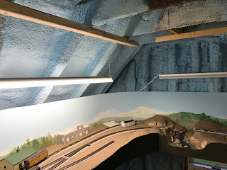
After masking the layout and backdrop with newspaper and then painting the collar ties, the next step was the lighting on the Willow Junction side. My original plan was to mount 1 X 2 boards along the rafters to attach the LED strip lights that I had purchased at the local big box store. After mounting the first of the 1 X 2 strips, I realized that the LEDs would be facing the back of the valance instead of facing down to the tracks and scenery. After considering ripping 2 X 2s at an angle to mount to the rafters with one side then facing down, I thought of another option. Why not just hang the original four foot LED shop light from the 1 X 2 I had mounted for the strip lights? Installing the hooks on the back of the 1 X 2 allowed for a reasonable positioning behind the future valance with the light shining down towards the modeled area. Completing this process, the lights are in place, and the various supports for the valance are also in place. I will prime the back of the "Masonite" and prep the track and airbrush it before the final instal of the valance.

Monday, April 30, 2018

Lighting and Valance Part 1

"Good" lighting and framing the scene with fascia and valance both add to the appearance of realism on a model railroad. I had a notion of how to do this on the 4th Subdivision from the beginning, but now I am actually working out the details. First of all, the attic location, with its angled ceiling, adds complexity to the process. Additional complexity is added by the uneven floors and roof of our older farmhouse.
First steps of lighting and adding valance
I hung the recently purchased 3' LED shop-lights from the roof rafters by installing hooks through the foam into rafters. Then it was easy to use the supplied chains to hang the three shop-lights over Willow Springs and the bottom of the "U."

The accompanying photo also shows the 2" x 2" that I screwed into the collar ties to hang the 16" valance. I had a 4 x 8 sheet of 1/8" tempered hardwood ripped lengthwise into three pieces about 16" wide. The 16" valance will work out to be around 13" inches from the plywood base of the layout. This works well for me, as I then don't see the blue foam above the backdrop, and it will be comfortable to reach in to the gap during switching operations.  It turns out that my wife, much shorter than me at 5'2", does see the gap. Ah, the best laid plans . . .

The shop-lights were up, but I still had to figure out a plan for getting power to them without having extension cords in a spider web all over the floor. I ended up mounting a scrap plywood cross piece across two legs, mounting a power-strip to it with cable ties, and dropping the cords behind the backboard to plug into the strip. It is convenient to just reach under the layout and flip one switch to turn on the layout lighting.

While we clamped part of the valance in place to see how it looked, I still need to work out the final details of mounting it, particularly at seams. The other side, the Willow Junction side, is going to be a bit trickier for both lighting and the valance. On that side I am going to try LED strip lights, and I am going to have to come up with a different technique for mounting the valance. The slate roof on that side of the house, over the decades, has developed a slightly parabolic shape rather than a consistent straight angle, so I didn't leave myself room for the 2"x 2" hanging strip. My next steps will be to figure out the LED strip lights, clean up the cord situation, and then move on to the valance for the balance of the layout.

Sunday, March 25, 2018

Where have I been?

I can't believe I haven't posted to the GNbranch blog in two and a half months! Well, first of all, most of my model railroad time and energy has gone into the formation of the new division: The Alleghany Western, or Division 12, Mid Central Region, NMRA. Rather than list what all has been involved, I'll just say that I have taken on a lot of duties in the process.

In the non-railroad part of my life, I have been substitute teaching around a day or two a week, and my wife and I have started a budget remodeling of our kitchen. While subbing is less of a time commitment than regular teaching, it is at least as exhausting.

At any rate, Spring is sort of here and inertia must be overcome. Last week, on my birthday, I went up to the attic to run over half of the planned operations in sequence, and it was fun!
Also, I recently purchased these three 3' LED shoplights at our local hardware chain for a very reasonable price. I think it is time to tackle the lighting and valance for the initial "U" part of the layout. I have an idea of how to do it, but the details will have to be worked out in the process. The valance in particular has been a gumption trap for a while, and it is time to break inertia by actually starting.

Monday, January 1, 2018

Elevator Complex - Feed & Seed Part 1

During December, I started a new structure for the Willow Springs side of the layout.

While I was originally going to build American Model Builders #706, Elevated Warehouse, as an office/warehouse for the planned grain elevator at Willow Springs, I decided to locate it across the tracks as a related feed and seed business. The first step of building this wood laser kit was to read through the instructions and check the parts. For the wood parts, I stained the parts with my standard Prego jar stain (70% alcohol, black ink, and raw umber acrylic paint). My plan was to stain both sides to reduce warping, but I missed one wall section interior side. After the stain dried I painted the exterior walls with Model Master Reefer White. Rather that trying to get complete coverage with the white paint, I followed a modified dry-brushing technique allowing some of the stain to show through the clapboards towards the bottom of the walls.


The next step was to remove the walls and floor from the carrier sheets and prepare them for assembly. I used a new #11 blade in a modeler's knife and a cutting mat to facilitate cutting the tabs holding the part onto the carrier sheet. From the beginning I planned on adding interior details and lighting to this simple structure. I used Google images to find photographs of feed store interiors, and resizing and splicing several together, I mounted them on one interior wall with Scotch Super 77 spray adhesive.Using the supplied floor risers and additional 1/8" square stock, I glued bracing to the wall sections with yellow carpenter's glue. I also glued 1/8" square stock to the underside of the floor, being careful to measure to avoid the floor risers and pier locations.

Up to this point, my process aligned well with the kit's instructions. My one significant divergence was to mount the doors and windows in the wall sections before I glued the walls together. I painted the door and window parts with Model Master Dark Tan before removing them from the carrier sheet and with a second coat after removing the parts. I mounted the sliding doors in an open position to allow the interior of the building to be more visible. On the interior of the track side wall, I scratchbuilt window and door molding, as this interior wall will be visible through windows and the open loading doors. To help assemble the multi-part peel and stick doors and windows, I fashioned a temporary jig from a small machinist's square and a metal ruler. This temporary jig can be seen in the photo to the left. As I assembled the doors and windows, I glued them into the wall openings. As the wall sections were completed, I glued the walls together, using the floor to square everything together.