
Now, with the open grid benchwork clamped in place, travel around the top of the stairs is definitely more convenient than it was with the fold-up staging deployed, the problem discussed in the last few posts. The solution is tight, but better.


When I positioned the plywood top on the benchwork in place in the attic, before cutting out a portion for the creek, I started having second thoughts about my plans for this new area of the railroad. Part of the issue is that extending the backdrop and/or the valance into this area is going to be tricky, at best, no matter what I do. I started thinking to myself, "What about using that area behind the existing backdrop as hidden staging?" This opened up a whole new possibility and a bit of a conflict: will the focus of this west end extension be on scenery or operations?
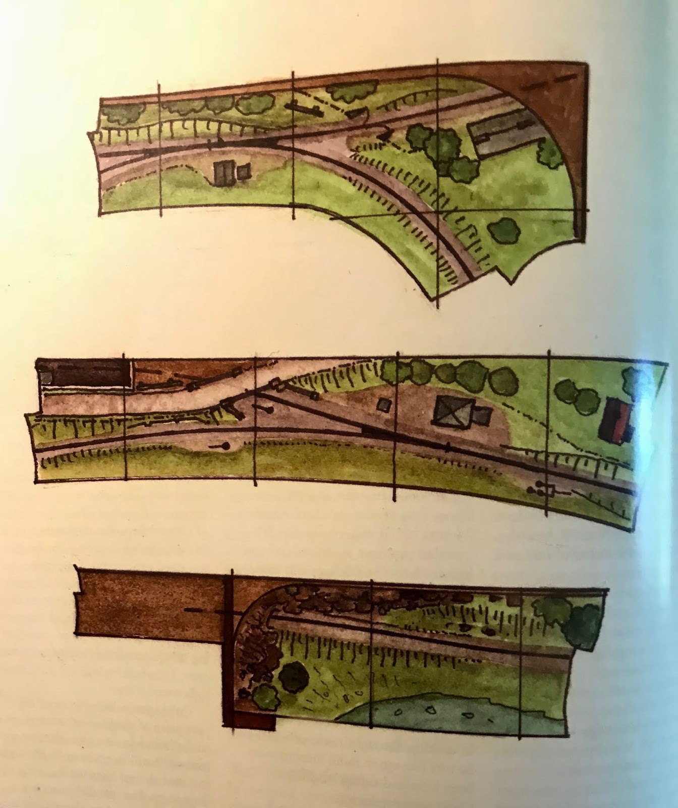 |
| Snapshot of Iain Rice illustration |
Despite investigating how a "bitsa" approach could add operating potential, I ended up going back to a scenery-based focus. Remembering why I am doing this, a tight squeeze at the top of the stairs, should remind me that this is not an ideal location for a "tower man" to be located. Also, yes it would be an additional train (or two: one out and one in), but really, it would travel four feet from staging to staging in this awkward location. Another consideration in making this decision is the overall mix of "empty" space or scenery-only space with operations-intense space. The first third of the eventual railroad, which I often call the initial U-shaped layout, currently has only one scenic break between track-work intense areas. Having a scenic break as this western
 extension's focus will hopefully lead to more of the kind of balance recommended by railroad planners such as Lance Mindheim. A final fortuitous bit of research in my stacks (my wife refers to them as "those endless piles") of model railroad magazines led me to Reference Sheet No. 390 from the Great Northern Railway Historical Society: "The Tunnels of the Montana Central Railway." In a different section of the Prickly Pear Creek Canyon from the one with the pony truss bridge mentioned in an earlier post, Tunnel 5 is a prototype for a concrete tunnel portal, curved track, and a short girder bridge that matches the terrain planned for this west extension. A snapshot of a page from this reference sheet is seen here, suggesting how to include steep hillsides to hide the sloping roof. This is what Tony Koester refers to as a Layout Design Element or LDE with, in this case, a focus on scenery. I think that I will of necessity compress an already tight scene and change the location, but use a bridge kit and tunnel portal that are closer to the prototype than the ones I have on hand.
With the decision made to go with a scenery-focused extension, I cut out an area for the creek from the plywood top and a plywood creek bed below. I left the bridge area in place until I have a kit and have it started. I also have the two legs cut to length and drilled to install leveling bolts. The next steps in approximate order are to:
- Attach creek bed and top plywood pieces to the frame
- Paint benchwork with white primer and legs with black paint
- Run DCC bus and install European style terminal blocks as needed
- Order Micro Engineering thru girder bridge and "concrete" style tunnel portal
- Attach cork roadbed and track
- Drop and attach feeders
- Figure out curved backdrop, valance end, and terrain
- Bolt the extension to existing benchwork, mount legs, and attach the (former drop-down, but now permanently up) staging.
No comments:
Post a Comment