Sunday, May 21, 2017

Willow Springs Under Way -- Track Laying Started

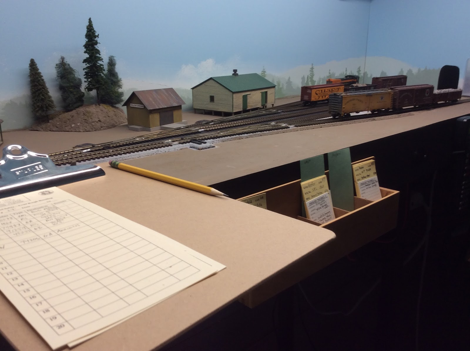
Willow Springs side of the layout, with track-work started.

I have started the track-work on the Willow Springs side of the layout, focusing on the mainline and the siding. In addition to positioning several of the mainline turnouts, cutting the track between them, and dropping feeders and frog jumpers for this first section, I went ahead and prepped all the other turnouts. I explained the step-by-step process for hidden feeders on this earlier post, and the process for prepping the turnouts is explained in this video by Luke Towan on Youtube. On this side I will be using slow motion turnout motors. A few years ago, on the layout of one of my Seattle modular friends, we witnessed that the Peco switch rod springs need to be removed when doing this; somehow, with the switch rod spring in place, the timing is off between the switch throwing and polarity of the frog changing which led to shorts.

Underside of Peco Electrofrog turnout with frog isolated (1),
point and stock rails soldered (2), and feeder wire soldered to
frog (4).
Having prepped the Peco Electrofrog turnouts for DCC friendliness on the rest of the layout and made the decision to skip the point rail jumper step, the process goes fairly quickly now:

  1. Snip jumper wires connecting center rails to the frog
  2. Solder point rails to stock rails
  3. Remove the Peco switch rod spring (since I will be using Tortoise switch machines)
  4. Solder green feeder wire to underside of frog
  5. Check continuity with multi-meter
  6. Trim off ties for rail for rail joiners
  7. Drill out holes for track nails at the underside dimples
While I had been planning on waiting on constructing the curved trestle bridge, I have decided to start on it as part of the  track-work for this side of the layout. That will have to be a different post.


Thursday, May 4, 2017

Willow Springs Under Way -- First Steps

Willow Springs ready for track!


After clearing off the clutter that had accumulated on the Willow Springs side of the layout, I finally prepped for track laying. A how-to description of the details of the process is on an earlier post. Basically, I followed a four step process:

  1. cut slots in the cork and drill holes for the switch machine actuating wires
  2. cut, sand, and glue on switch stand pads
  3. sand the cork bevels
  4. paint the cork with a color similar to the ballast.
Because installing a control panel for the Tortoise switch machines and a UTP for the NCE throttle will be needed for checking the wiring, I installed a four foot section of fascia now, rather than after the scenery is started. After cutting, installing, and painting the fascia section, I ran the cab bus wire from the initial UTP , repainted the metal panel, and cut a 1" X 2 1/4" hole in the fascia  to mount the UTP. I also installed two dowels as a throttle holder.

Thursday, April 27, 2017

Initial Operations

Initial operations at Willow Junction,
 testing track and operations plans.
With Willow Junction trackwork functional, I am able to start some initial operations on the 4th Subdivision. One conceptual change from my original operations plan is that the interchange track connects with the Northern Pacific (N.P.), not the Puget Sound and Badger River Rail Road (PS&BR). Several factors led to this change: a dearth of rolling stock ready for PS&BR, initial research into realistic shipping possibilities, and prototype possibilities (the freelanced 4th Subdivision would have intersected with the N.P. north/south line to Sumas, WA). In possible future expansion to the east, interchange with the PS&BR will be revisited. Not so much a change, but rather some fine tuning in the original plan, is the notion that the entire original layout is within yard limits with a "local switcher" or "road switcher" stationed at Willow Junction.

As realistic operations is one of my goals, I have begun collecting operating guidelines from a PDF copy of Consolidated Code of Operating Rules and General Instructions.-Revised 1946 as well as perusing several operations guides (How to Operate Your Model Railroad and Realistic Model Railroad Operation). So, for now, what I have come up with is an initial document to guide operations :

Rules Phase One    4th Subdivision


14.  Engine Whistle Signals
A short sound is designated by “0” and a long sound by a “- -"
0
Apply brakes -- Stop
--  --
Release brakes – Proceed Forward
0 0 0
Release Brakes – Reverse Back
--   --  0  --
Grade Crossing (last long extended)
Ring Bell when public contact possible and on bridges!


83 (B). Unless otherwise provided, a train must not leave its initial station on any subdivision, without a clearance endorsed with O.K., the time, and the superintendent's initials.
92. A train must not leave a station in advance of its scheduled leaving time.
93. Within yard limits the main track may be used, clearing first class trains when due to leave the last station where time is shown.
Within yard limits the main track may be used without protecting against second and inferior class, extra trains and engines.
Within yard limits second and inferior class, extra trains and engines must move at restricted speed.

104.  Unless otherwise provided, the normal position of a main track switch is for main track and must be lined in that position, except when changed for immediate movement through it. Switches must be properly lined after having been used.

As Willow Junction and the east staging tracks are what I have to work with, my initial operations is limited to sorting cars. I have bill boxes, a revised switch list (prototype based), and car cards and waybills set up. Essentially I started with a few cars on the layout and the N.P. interchange with the goal of sorting them into propers (rolling stock destined for Willow Springs locations) on one yard track and Westbound cars on the other. Classification fun!

Monday, April 3, 2017

Bottom of the "U" - Track Laying and Wiring


In continuing the track laying through to the bridge at the bottom of the "U," I tried two new techniques and found that I needed to improve on my basic track-work. As I was learning and practicing how to do this, I will present it in how-to format.

Mainline and Other than Mainline Track

While trying to troubleshoot a mistake in placement for my feeder wires (details will follow later) I found myself remembering the article, "Mainline and Other than Mainline Track," that I had just read in the March 2017 NMRA Magazine. In the article, David Heinsohn discussed a take away from clinics put on by Stephen Priest and family. In short, he suggested treating the mainline differently from other than mainline tracks. To accomplish this he suggested removing random ties and treating the ballasting differently in non-mainline track. As I was going to have to remove a tie from the middle of the spur to correct a mistake, I elected to follow this technique on the spur involved. The tools I used are shown in the photo to the upper left: A hobby knife with a chisel blade, a pair of needle nosed pliers (made here in my hometown), and a rolling die for randomness. Later, when I turn to ballasting the track, I will revisit the article for ballasting and weathering ideas.

Sequence is Important for Under the Track Feeder Usage


So, I learned the hard way that the steps in powering the track with under the track feeders should follow a specific sequence. It is also important to double check between each step!
  1. Measure and cut each piece of track to the exact length. Flex track must be bent in its final shape to mark the correct length for each rail. Remember that powered frogs will need insulated joiners; the rails will need a slight gap to accommodate them.
  2. Remove the ties and file the rail ends to accommodate the joiners. The bottom should be filed flat, the end filed perpendicular, and the web of the rail filed clean. 
  3. Bend flex track into place and identify approximate feeder location. Check under the roadbed: is the area open and will the bus be accessible? Also, if possible, use already existing voids in the plastic connectors between ties.
  4. Mark the exact location of feeders on each rail (with a Sharpie) with the flex track bent. Also mark and remove any plastic under the rail. The marking should be correct with any bend in the final track position.
  5. With the track in place, mark the location for the holes through the roadbed and benchwork directly under the marked rail feeder locations.
  6. Go ahead and drill the holes slightly larger than the size of the feeder wire.
  7. Solder color correct feeders long enough (too long is easier to fix than not long enough) to reach the bus. Remember that the track is upside down; my rule of "black out" did not apply in this case. Also remember that one of the rails may slip side to side. Make sure that the location between the ties is correct, not just the location on the rail.
  8. Drop the feeders through the holes and slip the track into place with joiners installed. One fix if it is close but not a perfect fit is to remove the track and enlarge the holes through the roadbed.
  9. Once satisfied with the fit of several pieces of track, connect the feeders to the bus with suitcase connectors.
  10. Check visually, with a multimeter, and by running locomotives before soldering the joiners.

Using Tortoise Switch Machines to Power Turnouts


Doing as much of the soldering as I could before
installing under the layout was one of my goals.
Here at the bottom of the "U" and on the upcoming Willow Springs side of the layout, I will be using switch motors rather than just throwing the turnouts by hand. While I have used Tortoise switch machines in the past, I have not used the internal SPDT switches to power frogs. The process I used on wiring this wye seemed like the way to go.  In general, I will not be describing every aspect of basic Tortoise installation, but focusing on wiring the switch motor.

First of all I created an installation template by cutting out the master from the instruction sheet and mounting it to .080 styrene with double stick tape. Using the template I was able to mark the underside of the layout for the mounting screws. I drilled the holes and mounted the two #4, 1/2 inch screws on the opposite side of the Tortoise location.

The next step was to solder the power wires and the feeder wires to the appropriate pads on the Tortoise printed circuit board before installing the motor under the layout.  As the plan is to control the turnouts with Berrett Hill's Touch Toggle system, I opted to run 18-2 thermostat wire from the turnouts to the future location of the control panel. One issue with this option is that the holes in the #1 and #8 pads had to be enlarged for the #18 wire. Before soldering the red and black feeder wires to the #2 and #3 pads I had to use a multimeter set to ohms to determine which feeder should connect to #2 or #3 to make the internal toggle connection to pad #4, where the green feeder from the frog will be soldered after the Tortoise is in place. First, I determined that in this application, with the throw-arm screw to the left, the frog will need black power and with the throw-arm to the right, the frog will need red power. Then I was able to use the multimeter to determine which pad should be red and which should be black. At that point I was able to carefully solder the four wires to their respective pads. Care must be taken to not cross any of the pads with solder.
Wye Tortoise in place, although the frog feeder wire
could be dressed.

Then I moved to under the layout. First, the green feeder was soldered to the #4 pad under the layout but before installing the motor. By soldering before installation I was able to avoid soldering over my head. After installing the Tortoise and adjusting the fulcrum for solid point contacts, I was able to finish up the wiring. I connected the red and black wires to the red and black track bus wires with suitcase connectors. Finally I drilled holes through the benchwork and ran the turnout motor wire through to the location of the Touch Toggle control panel. 

 I am feeling much more confident about the wiring and track laying for the balance of the layout after fine tuning and practicing my techniques on this wye and spur track at the bottom of the "U."


Tuesday, March 14, 2017

Willow Junction -- Track Laying and Wiring


Finally, I can run trains from the East Staging onto the Willow Junction side of the layout. Why has this taken me so long? Well, I convinced myself it was going to be hard, so I kept doing other things. Also, I was trying to improve my technique, which meant combining what I had previously thought of as two separate processes, laying track and wiring, into one. By soldering the feeders under the rails, it hides the soldered joint, which is a scenic improvement, and by powering the frogs, the layout should operate smoothly. This forced me out of my comfort level forcing me to push myself into improving my skills. I know, one does not learn by avoidance, but through practice. I had a few bumps along the road, but what follows is a description of my process.

First of all, I chose to have the DCC system fully installed and ready to go before laying the track and wiring it. The good: I was able to identify a loose solder joint to one of the isolated frogs during the installation process, rather than later. I didn't have to tear up finished work. The bad: lots of rabbit holes and work to be completed before track could be started! The ugly: I did not understand that the "Frog Juicer" works on electrical "draw." In testing as I went, I convinced myself that something was wrong when the frog "polarity" did not change when the points were changed. The board does not make that change until it detects the "short" in the current draw from a locomotive going through the point. I spent a lot of time and frustration trying to troubleshoot a problem that was not a problem.

Feeder wire and track ready for tinning
on the engine spur.
The track in this portion of the layout is code 83 Atlas Superflex with Peco code 83 Electrofrog turnouts. The process for prepping the turnouts is described in an earlier post. When soldering feeders to the underside of the rails, a major difference is the amount of measuring and rechecking as one proceeds. Not only does the track have to be the correct length, but the feeders have to line up with holes through the cork and layout. The Atlas flextrack has three spots open from the underneath to solder feeders. If these do not work, gaps must be cut in the plastic between the ties under the rail. At the same time that the rail is marked for feeder location, the location for the holes through the roadbed must be marked. While a sharpie works well for marking, I struggled with remembering that one rail in this flextrack is quite willing to slide out of its original position when I wasn't noticing. By tinning the underside of the rail and the feeder with a bend in the end so it fits in the plastic gap, the actual feeder soldering goes quite smoothly. Triple checking locations is crucial.

Photo of draft wiring diagram with
approximate feeder locations marked.
As the track was installed, I would connect the feeders to the bus and the frog wires to the Frog Juicer. I used red and black feeder wire, matching the bus colors, to keep the growing collection of wire under the layout organized. I also followed or altered the draft wiring diagram to keep a record for future troubleshooting. I used green (or white with green added with a sharpie) for the frog wires. As the rails coming out of the frog were insulated, feeders were required between the turnouts. After finishing one small section, I would check it with a multimeter and with a locomotive before moving on to the next.  Once the entire Willow Junction side was working smoothly, I soldered the rail joiners and tested one more time.

Before I can paint the track, I still need to scrub rail joints with denatured alcohol and fit in missing ties. But, I now have a small switching area in which I can run trains as I move on with a bit more confidence to install the track on the rest of the railroad.

Wednesday, March 8, 2017

The 8 Cent Weight Fix


In setting up my rolling stock collection for the railroad, I noticed that I had a preponderance of Great Northern rail cars. In recent research (Jeff Wilson's Freight Cars of the 40's and 50's -- a Christmas Gift) I read that about 50% should be home road, 25% other neighboring roads, and 25% more distant lines. One of the few more distant line cars that I already own is an Erie gondola that I picked up years ago at a train show. The initial problem was that it was underweight when empty, so it would not meet the rolling stock standards that I have established for the layout.

The solution was in the coin jar. Adding eight pennies brought the weight of the car up to the recommended four ounces. In addition to meeting standards, I wanted to add some weathering to the car. I recently read a weathering-tips article online that discussed "not-so-empty" gondolas. What follows is a description of how I brought Erie 45232 up to standard and improved its weathering.


The first step was to glue the eight pennies onto the gondola's original floor with gap filling medium CA. Then using .060 styrene, I scored and snapped a new floor to fit over the pennies. Using an emery board, I sanded the floor to fit, and then glued it into place with the CA. After the CA dried I brush painted the interior of the gondola with Model Master Rust and Grimy Black flat acrylic paints. In hindsight, masking and spray painting the interior with a primer would have meant fewer coats of streaky brushed-on paint. I'm finding that brushed-on Model Master does not cover as well as Poly Scale did and it has a bit more gloss to it. By using Bragdon weathering powders as well as glueing in some strip wood and coal with white glue, I was able to detail the interior and freshen the weathering of the exterior of the newest addition to my fleet. The next step will be to scratchbuild a pipeload using straws; maybe I can keep that to eight cents as well!

Sunday, February 5, 2017

West End "Fold Up" Staging -- Part 1


I designed the staging for the west end based on David Popp's "Swing Out Section" for the Winston-Salem Southbound on the Model Railroader Video Plus subscription web site.  Since the staging at the end of the layout is opposite the top of the attic stairs, it needed to be removable when not in use. The significant differences in my iteration were that I used a 1 X 6 instead of a 1 X 4 and that mine is a bit longer. That will allow for three track staging, holding a similar amount of rolling stock as the completed East Staging.

I followed David Popp's plan for t-girder construction and single fold up leg for the lightweight, hinged staging. Since I don't have an air gun, I used a combination of Robertson trim screws with a #1 square drive bit in my drill motor and truly old-school finishing nails and hammer for initially holding the glue joints during construction.

 As seen to the right, the staging framework folds up under the layout. By adding a 1 X 2 across the nearest legs I am able to hang the staging section attached with hook and eye hardware. While not visible in the snapshot, I can also hang the C clamp that secures the staging at the hinged attachment point on this 1 X 2.

With the final benchwork for the initial layout complete with this foldout section, I can focus on the completion of track work and wiring.