Monday, April 18, 2016

Setting Up the DCC System

Over the last few days we have had some beautiful spring weather, and in addition to doing some yard work, I have gotten up into the attic to work on the layout. Now that several of the sections of benchwork are fully installed, I tackled setting up the DCC system (NCE Power  Pro 5 amp) that I brought from Seattle.

First of all, while I ordered an update EPROM chip quite awhile ago, I had never installed it. It was not that hard, once I got up the gumption to do it. NCE had instructions on their website. First, I removed the four screws and slid off the cover. Being careful not to pry under the holder, the old chip popped right off with gentle prying with a small screwdriver from below. Following the instructions, I positioned the new chip using the half moon to guide the orientation. Two of the prongs tried to splay out rather than slide into their slots. As I was going slowly and carefully, I was able to remove the chip, straighten the prongs, and install the chip with all the prongs in place. Hopefully it was a successful install!


I sketched out several designs for a shelf under the layout to hold the command station, transformer, and power strip. I settled on one that basically has the shelf bolted to a support rail between two legs. I made the shelf from 1/2" plywood with a 2x2 glued under it. After painting everything a flat black, I bolted the 2x2  to the rail I had installed between the legs. In hindsight I should have used a 2x3 because the 2x2 left too narrow a space for my drill motor to fit at a true perpendicular for installing the carriage bolts. I ended up with rough framing tolerances rather than finish carpentry, but it worked.
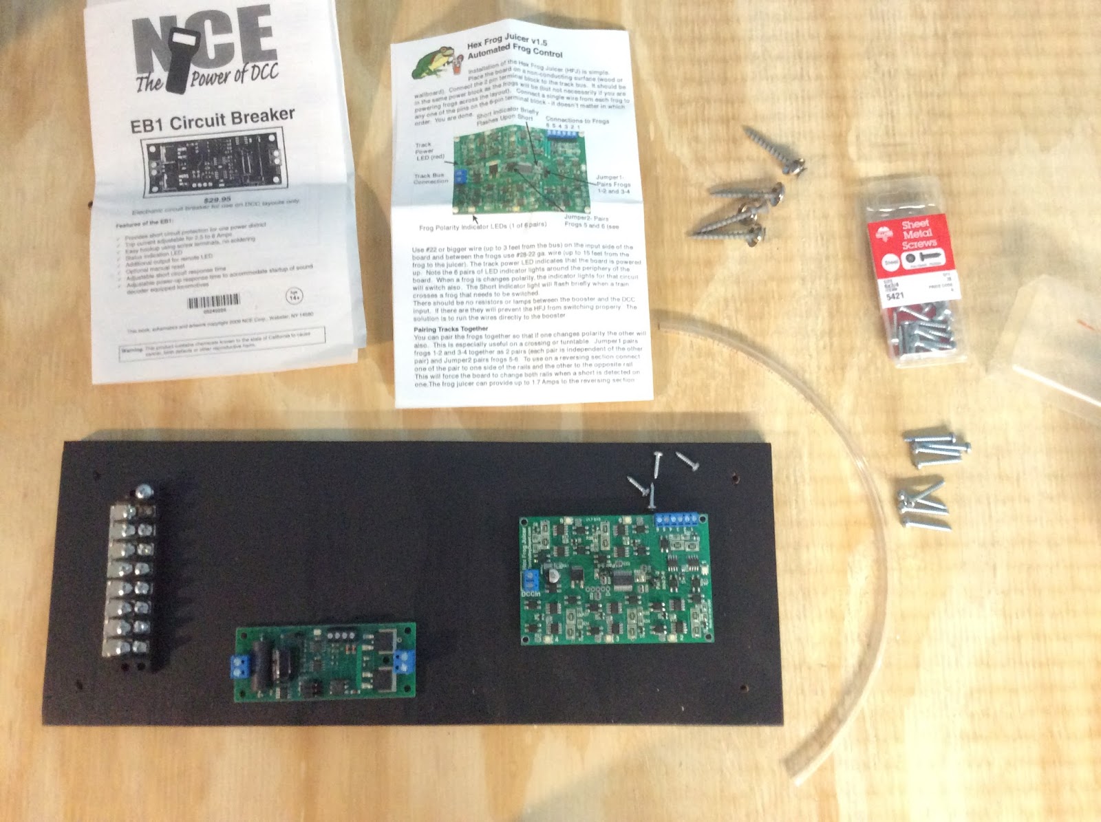

The next step was to build a  board to mount some of the components of the system. For this initial U shaped layout, I am planning on having two power districts with each protected by a circuit breaker. This board, made from scrap plywood, was designed to hold the two NCE EB1 breakers (I need to order a second one) as well as a Tam Valley Depot Hex Frog Juicer to power the frogs of the turnouts in the interchange yard.

I used a barrier strip I had on hand, mounted with  #6 1/2 inch pan head screws. For the EB1 boards I fashioned standoffs from plastic tubing and mounted them with #6 3/4 inch pan head screws.  I set a stop on my NWSL Chopper at approximately 3/8" and cut all eight pieces of tubing to use as standoffs. The Frog Juicer had plastic bumpers already installed under the circuit board, but I had to find some #4 screws to mount it. While on the work bench I connected the one circuit board I have on hand and the Frog Juicer to the barrier strip..

After mounting the board to another pair of legs, I ran the DCC output wires from the command station to the terminal strip. The system is ready for me to start the bus for the first power district and order the second EB1.

The one thing that I haven't quite figured out yet is the location of a program track. I'm leaning towards adding it to the staging module. Then I could start the bus and power the staging tracks to use as test tracks and trouble shoot the system.


Thursday, April 14, 2016

Goal Setting

While I have been occupied with other parts of my life over the last several months, I think that the slowdown in progress on the layout had a deeper cause. In a recent post on one of his blogs, Shelf Layouts, Lance Mindheim talks about "subtle traps that can sap enthusiasm." One that he mentions in particular is "not hitting personalized completion milestones" in our internal timeline. His solution is to front load with targets.

Mindheim Targets:

  • Benchwork Complete: 3-6 months
  • Some Train Running:  3-6 months
  • A scene or two finished:  1 year
  • All three:  18-24 months
With his targets in mind and an awareness that I have to fit the railroad in with other parts of my life without progress coming to a standstill, I have come up with a list of my own. It is intended as both a to do list and a goal setting motivator.

To Do:
  • Benchwork finalized and in place
  • Workbench and materials organized
  • Regular posting to the blog
  • DCC components set up
  • East staging and a program track wired
  • Start work on rolling stock and loco roster and maintenance
  • Start some track work
  • Start a building or bridge
  • Design the fascia and valence 

Tuesday, April 5, 2016

Benchwork for the Bottom of the "U"

Progress has certainly slowed over the winter; however, the benchwork for the bottom of the "U" is in place temporarily. As I mentioned in an earlier post, this section had to be slightly reduced in size from the original plan. I drew up plans with the new size continuing with basic open grid framing. One nod towards cookie cutter benchwork in this section is the cutout for a creek bed, a scenic element, between Willow Junction and Willow Springs.

Bottom of the "U" Benchwork under construction on sawhorses
in the attic. The workshop in the barn has been too cold!
This cutout turned out to be a bit of a gumption trap as I hadn't really tried cookie cutter benchwork before. The open grid frame itself was constructed in the traditional manner, with the exception of a 1" X 2" frame member supporting the creek bed. After cutting the plywood, I cut the frame down for the creek bed insert and attached 1" X 2" supports along the bottom of the front and back of the frame. Both the location of the future pile trestle and the triangular plywood extension are visible in the photo to the left. This side of the bottom of the "U" will not have a corner section; rather, it will be the two rectangles bolted together.

The plan is for the back of this section of the benchwork to rest on an L girder ledger with one leg supporting the front and the ends bolting to the adjacent sections.  I will need to trim some of the blue foam and mount the next section of backdrop before permanently installing this section. The ledger and the location are visible in the photo to the right.

Friday, January 22, 2016

Rationale for the Railroad Part 3 - Planning for Operations

The railroad will be a part of a freelanced 4th Subdivision of the Cascade Division of the Great Northern. The 4th Subdivision travels eastward from Port Gulick Bay, intersects with the North/South GN mainline at Ferndale, WA, and then travels into the Cascade Mountains to the town of Greenstone. Port Gulick Bay, on the Puget Sound, has potential for a small shipyard, bulk petroleum operation, lumber shipping, log dump, lumber mills, and canning operations. Located in Whatcom County, and inspired by the 3rd Subdivision in Skagit County, the railroad has a heritage of support to timber and agricultural production. Plus, in a totally fictional history, a rich series of veins of ore were discovered in the Cascade Mountains, near the Badger River, leading to the founding of Greenstone and several mines. Copper and silver ore continue to be mined into the 1950's with the ore shipped by rail to the smelter in Tacoma.

The first part to be built is an interchange junction of the 4th Subdivision with the Puget Sound and Badger River Railway, a logging road inspired by the Puget Sound and Baker River RR, east of the Mainline at Ferndale, but still in the valley/lowlands. The interchange is at Willow Junction and the initial layout also includes Willow Springs, a station on the 4th Subdivision. Willow Junction includes a small yard and engine facilities for the road switcher stationed there. Willow Springs includes several  opportunities for switching.

First-draft track plan: Willow Junction at the top with Willow Springs at the bottom.
Among the possibilities for industries at Willow Springs are a box factory, canning company, produce warehouse, grocery distributor, team platform, fuel company, freight house, and small foundry. Any of these have prototype examples in the lowlands of Skagit or Whatcom counties. While not shown on the track plan, staging will be provided at both ends of the "U" shaped initial layout.

The operating scheme is designed for solo operations or operations with two or three operators. Car movements will be orchestrated using car-cards and waybills as well as switchlists. Train movements will essentially be sequence operation, although a time element could be added. One small scheduled passenger train will pass through Willow Springs eastward and then return later in the day. One scheduled freight, a turn from Port Gulick Bay will pass through daily and return.  The turn may drop off or pick up cars at the runaround, while the Willow Junction road switcher will be in charge of  spotting the cars and blocking cars for pickup.


Monday, January 11, 2016

Cork Roadbed

Over the past week or so I have started the trackwork on Willow Junction (one side of the U-shaped initial layout in the attic) by laying cork roadbed for this small yard and interchange. In this post I will attempt a "how to" approach to the process.

Materials

Materials needed to lay cork roadbed

  • Cork
  • Sanding block
  • wood glue
  • small nails
  • needle nose pliers
  • hammer
  • paper towels
  • utility knife with sharp blade
  • pencil and sharpie
  • metal rule
  • putty knife
  • spackle
  • brush or shop vac


First Steps

  1. Make sure all track center lines and turnout locations are marked on the sub-roadbed (plywood in my case.)   
  2. Split the cork.
  3. Glue down the cork strips (with the bevel to the outside) following the centerline and then tack in place with small nails just into the plywood. Remember, the nails will be removed after the glue dries.
  4. Offset the cork strips to avoid ends butting side by side.
  5. For turnouts glue and tack just the outer strips.


Turnouts


For the interior of the turnout, measure by overlapping and then mark with a pencil or sharpie in order to make an accurate cut.  The cut will first be a taper and then trimming the bevel of the cork so it fits between the existing cork strips. I found that I was fitting the cork strip that followed the divergent route first before the strip following the straight. Both should be test fit and adjusted before glueing either of them in place.

Finishing Up the Cork

  1. Allow the glue to dry overnight and remove the small nails.
  2. Sand the bevel to remove the ridge left along one edge after splitting the cork in half. Some people recommend doing this before installing the cork, but I find it easier to do after the cork is glued in place. Just make sure it is done before painting the cork or installing track. 
  3. Spackle any gaps in the turnout splice work. I spackled the nail heads in the plywood at the same time.
  4. It might be a good idea to paint the cork at this time, at least flat black under turnout locations. On the other hand, it might be prudent to finalize track placement and drill holes for turnout controls before painting.

Special Applications for Willow Junction


The two yard tracks were trimmed square as they were glued down, while the mainline cork offsets the plywood for later final trim when staging is attached.

The cork abuts a cedar shim as the interchange towards the front will be code 70 track representing the Puget Sound and Badger River Railroad, a lumber line.

The cork for the siding in the back abuts the piece of gatorboard that will be the base for the construction of a small engine house. I learned this technique from Pete Gulick, one of my modular railroad friends in Seattle.

Friday, January 1, 2016

Trackwork First Steps

Yesterday I transferred the paper track plan for Willow Junction to the layout  by establishing base lines on the plywood, laying out the turnouts, and penciling in the centerlines.


 I marked the turnout ends as well as lines at the switch rod location. (While I am not planning on using switch motors here, I will drill holes in case I might want to add them in the future.) The one change from the track plan was to locate the switcher engine house track at 14" from the edge instead of 15".

Laying out Willow Junction's track plan: without a backboard in
place, the sprayed-in, closed cell foam insulation is visible.

The next steps before actually starting to lay track are to lay the cork roadbed and to modify the turnouts. I have the cork, track, and turnouts, but the turnout pads are on backorder so I may have to  splice the turnout cork from straight sections. David Popp on MRVP has a good video on modifying turnouts as a part of the Olympia Logging video series. Also, the Peco instructions that came with the Electrofrog turnouts are clear and helpful. It looks like there are four steps to turnout modification:

  1. Connect the point rails and stock rails
  2. Construct point rail jumpers at the hinge
  3. Remove wires connecting the center rails to the frog and use insulating rail joiners at end of center rails past the frog
  4. Attach feeder wire to frog

Wednesday, December 16, 2015

Benchwork - First Steps


While I jumpstarted building benchwork earlier this fall by preparing a corner for a backdrop "how-to" presentation, putting it into action in the attic is happening just now.


After moving to Northwest Pennsylvania last summer, I found myself somewhat in limbo as far as my participation in the NMRA activities.  Because of my new address I was assigned to a division of the Niagara Frontier Region that was "inactive." Before much time passed I found that the NMRA National reassigned the members of the affected counties to two divisions of the Mid Central Region. In joining my new train group: The Western Reserve Division, Division 5 of the Mid Central Region, my first participation was to prepare a presentation on backdrops for their annual "Building A Model Railroad" event. I shared my bare-bones corner with a hardboard backdrop and created a handout of backboard ideas (located on Backboard Overview  page).

Flash forward six weeks. After building a second section of open grid benchwork and setting it up in place, I realized that I had misjudged (by a few inches) the size of layout that would fit under the roof rafters given the benchwork and backboard height I desired. So, in the last few days I have:
  • Installed a permanent L-girder ledger  
  • Started mocking up the plan in place on the layout
  • Redrew the track plan with an adjusted bottom to the "U"